
Pitch
1.25 mm, Single Row
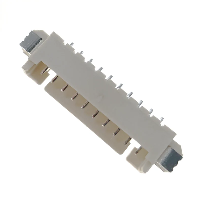 Product image is temporarily unavailable
Wire connectors
Series specification range: Pitch: 1.25 mm, Single Row · Positions: 2 / 4 / 6 / 8 / 10 Pin
Parameters may cover a series or several configurations. Confirm ratings for the selected contact count, dimensions and termination.
Wire-to-board connector. Wire-to-board connector. Series configuration parameters: Pitch: 1.25 mm, Single Row; Positions: 2 / 4 / 6 / 8 / 10 Pin; Mounting type: right angle 90°, SMT Gull-wing with Hold-down Solder Nails.
Discuss this product requirement1.25 mm, Single Row
2 / 4 / 6 / 8 / 10 Pin
right angle 90°, SMT Gull-wing with Hold-down Solder Nails
Solder
1.0 A per contact
Parameters may cover a series or several configurations. Confirm ratings for the selected contact count, dimensions and termination.
| Durability | High |
|---|---|
| Termination style | Solder |
| Pitch | 1.25 mm, Single Row |
| Positions | 2 / 4 / 6 / 8 / 10 Pin |
| Mounting type | right angle 90°, SMT Gull-wing with Hold-down Solder Nails |
| Recommended Mating Cycles | 30 cycles (tin plating); 500 cycles (Gold Flash) |
| PCB Pad Pitch | 1.25 ± 0.10 mm |
| Rated current | 1.0 A per contact |
|---|---|
| Rated voltage | 125 V AC/DC |
| Maximum Contact Resistance | ≤20 mΩ |
| Minimum Insulation Resistance | ≥100 MΩ |
| Withstanding Voltage | 250 V AC / 1 min |
| Plating | tin plating |
|---|---|
| Housing material | LCP / PA66, UL94 V-0 Flame Retardant |
| Contact material | Brass |
| Plating | Tin over Nickel (Standard); Gold Flash over Nickel (Optional) |
| Temperature range | -40 To 85 °C |
|---|---|
| Operating temperature | -25 ℃ ~ +85 ℃ |
| Connection type | Snap-On |
|---|---|
| Contact | Brass With gold plating Over 50U |
| Mating Direction | Horizontal Side-Entry |
After selecting the connection configuration, review its dimensions, pin assignment and installation requirements. Include the required configuration in your request.
Request this product drawingPitch: 1.25 mm, Single Row. The PCB footprint or mating interface must use the pitch of the selected configuration.
Positions: 2 / 4 / 6 / 8 / 10 Pin. Where a range or multiple options are shown, select the required count and pin assignment.
Mounting type: right angle 90°, SMT Gull-wing with Hold-down Solder Nails. Check installation clearance and mating geometry for this configuration.
Termination style: Solder. Check installation clearance and mating geometry for this configuration.
Share the model or required specification, quantity and delivery target.
lyxconnector.com